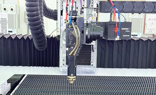
Optimizing Gas Pressure Settings for Stainless Steel Laser Cutting
Introduction
In the world of precision stainless steel processing, laser cutting has emerged as a go-to method because of its high precision and flexibility. The gas pressure setting of auxiliary gases is a crucial factor that impacts both the quality and efficiency of the cutting process. It directly influences the smoothness of the cut edge, the size of the heat - affected zone, and the amount of slag left behind. In this blog post, we'll dig deep into the optimization of gas pressure parameters, backed by real - world examples and practical operation guidelines, to help you achieve better results in stainless steel laser cutting.
I. Three Core Functions of Gas Pressure in Laser Cutting
1. Slag Removal Mechanism
During the cutting process, high - pressure gas (either oxygen or nitrogen) forms a fast - flowing air curtain. This curtain quickly blows away the molten metal droplets created by the laser beam. According to experimental data, when the gas pressure is too low, the slag adhesion can increase by more than 30%, which in turn raises the roughness of the cut surface by 2 - 3 grades.
2. Thermal Control Technology
Through gas convection cooling, the width of the heat - affected zone (HAZ) can be reduced to a range of 0.1 - 0.3mm. When working with thin sheets, precise control of gas pressure is essential to avoid thermal deformation and maintain dimensional tolerances within ±0.05mm.
3. Chemical Synergy
- Oxygen Combustion Support: In carbon steel cutting, oxygen can boost the cutting speed by 40%. However, in stainless steel cutting, the heat from oxidation can cause the edges to harden.
- Nitrogen Protection: Working in an inert nitrogen environment can result in oxide - free cuts, with a surface roughness of Ra ≤ 1.6μm. This makes it ideal for high - demand applications such as in the medical and food machinery industries.
II. Dynamic Matching Guide for Gas Pressure Parameters
(A) Standard Parameter Matrix
|
Material Thickness (mm)
|
Oxygen Cutting Pressure (Bar)
|
Nitrogen Cutting Pressure (Bar)
|
Typical Cutting Speed (m/min)
|
|
1 - 3
|
0.8 - 1.2
|
1.5 - 2.0
|
6 - 12
|
|
3 - 5
|
1.0 - 1.5
|
2.0 - 2.5
|
4 - 8
|
|
5 - 8
|
1.5 - 2.0
|
2.5 - 3.5
|
2 - 5
|
|
8 - 10
|
2.0 - 2.5
|
3.5 - 4.0
|
1 - 3
|
(B) Adjustment Strategies for Special Scenarios
- Material Difference Compensation
316L stainless steel contains molybdenum, which gives it a 15% lower thermal conductivity compared to 304. To ensure proper slag removal, the gas pressure needs to be increased by 12%.
- Critical Thickness Handling
- Thin Sheets (≤3mm): Pressure fluctuations of more than ±0.1Bar can lead to burrs. It's advisable to use a constant - pressure control system.
- Thick Plates (≥8mm): The gas pressure should be adjusted along with the beam mode. When using long - focus lenses, the pressure limit can be raised to 4.5Bar.
III. Systematic Optimization of Synergistic Parameters
(A) Gas Purity and Cost Balance
- Oxygen Grade: Industrial - grade oxygen (99.5%) is suitable for general cutting tasks. For a 40% reduction in the thickness of the oxide layer, high - purity oxygen (99.95%) can be used.
- Nitrogen Economy: Nitrogen cutting costs 2.8 times more than oxygen cutting. It's recommended when a surface roughness of Ra ≤ 0.8μm is required.
(B) Nozzle Engineering Design
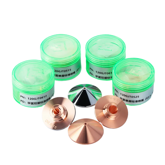
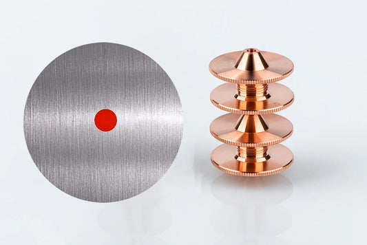
- Diameter Selection: A 1.5mm nozzle paired with 2.0Bar of pressure offers optimal focusing. If the nozzle wear exceeds 0.1mm, it should be replaced.
- Maintenance Cycle: The nozzle tips should be inspected every 5,000 meters of cutting. Compressed air backflushing can be used to clean off any metal microparticles.
(C) Power - Speed - Pressure Triangle Model
Take, for example, a 3kW fiber laser cutting 5mm stainless steel:
- Oxygen Cutting: With a pressure of 1.8Bar, a speed of 3.2m/min, and a heat input of 1.7kJ/mm.
- Nitrogen Cutting: At a pressure of 3.0Bar, a speed of 2.1m/min, and a heat input of 2.5kJ/mm.
IV. Operation Specifications and Fault Diagnosis
(A) Safety Operation Essentials
- Gas pipelines must pass a pressure test at 1.5 times the working pressure and be equipped with real - time pressure sensors.
- Dual shutter protection systems should be used to prevent any secondary damage from laser reflections.
(B) Process Debugging Flow
- When doing the first - piece testing, create a stepped parameter table that records the cutting effects at pressures ranging from 1.0Bar to 3.0Bar.
- Use vision inspection systems to measure the cut perpendicularity, aiming for a value within ±0.5°.
(C) Typical Fault Solutions
|
Fault Phenomenon
|
Root Cause Analysis
|
Solution
|
|
Bottom slag accumulation
|
Insufficient pressure + slow speed
|
Increase pressure 0.3Bar + reduce speed 15%
|
|
Excessive kerf width
|
Nozzle - workpiece distance variation
|
Calibrate Z - axis following system
|
|
Thick oxide layer
|
Nitrogen purity <99.99%
|
Replace gas supplier
|
V. Directions for Intelligent Upgrades
- Adaptive Control System: Incorporate AI algorithms to adjust the gas pressure in real - time based on the reflection signals from the molten pool.
- Digital Twin Technology: Use virtual modeling to simulate the cutting effects under different gas pressure parameters, reducing the need for costly trial - and - error.
- IoT Platform: Build a cloud database of equipment parameters to enable collaborative optimization across multiple factories.
Conclusion
Optimizing gas pressure in stainless steel laser cutting is a complex but rewarding task. It requires considering various factors such as material properties, equipment capabilities, and process requirements. By setting up standardized parameter systems, implementing preventive maintenance, and using intelligent monitoring technologies, you can achieve a 25% increase in cutting efficiency and bring the scrap rate down to less than 0.3%. Companies should also focus on training their process engineers to shift from an experience - based approach to a data - driven one for more consistent and efficient production.

