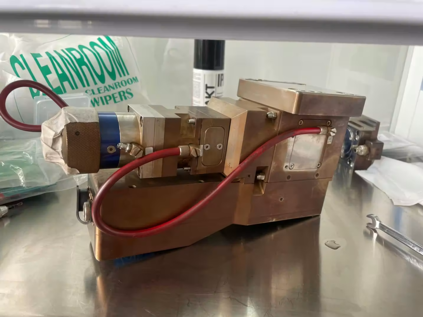
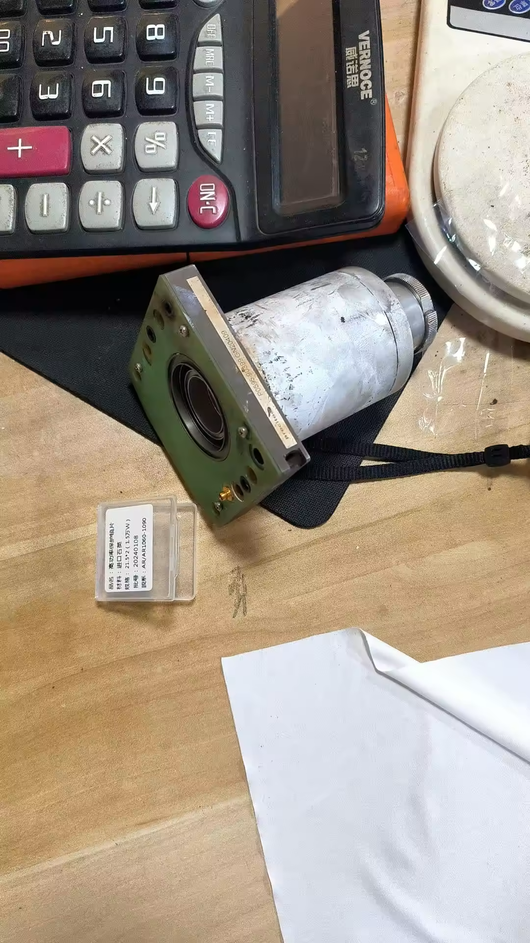
A laser cutter is an automated cutting tool that employs a laser beam produced by a laser generator to rapidly heat the material to a melting or vaporizing temperature, after which it vaporizes to form holes. As the laser beam passes across the material, the holes constantly develop into tiny slits, completing the material cutting process.
Whether you are a newbie or a professional, you may encounter a variety of failures while using CO2 laser cutters and fiber laser cutters on a daily basis. So, how do we tackle these problems? The following is the 16 Practical Solutions to Most Common Laser Cutter Problems.
Most Common Laser Cutter Problems
Angularity in cutting
- Compensate for the reverse clearance (change in the platform configuration);
- Check the meshing of gears and racks;
- Check the motor installation to ensure that the spacer is installed correctly and the coupling is firmly fastened;
- Check whether the slider screws are firmly fastened.
Cutting ripple problem
- Cut by pressing the plate by hand and check the cutting effect;
- Check whether the machine tool leveling pads and table frame are unstable and shaking. It is not allowed to place unstable and unreliable profiles under the leveling pads;
- Adjust the cutting parameters;
a. Set in the software to reduce the following sensitivity;
b. Set in the software to increase vibration suppression;
c. Adjust servo parameters; - Compensate for the reverse clearance (change in the platform configuration);
- Check whether the cylinder locks the exchange platform;
- Whether the laser head and related parts are firmly fixed;
- Check the motor installation to ensure that the spacer is installed correctly and the coupling is firmly fastened;
- Check whether the slider screws are firmly fastened;
- Check the meshing of the X and Y axes, requiring 0.06 – 0.08mm;
- Replace the X and Y reducers and motors.
Poor cutting accuracy
- Whether the laser head and related parts are firmly fixed;
- Adjust process parameters and servo parameters;
- Compensate for the reverse clearance (change in the platform configuration);
- Check the meshing of the X and Y axes, requiring 0.06 – 0.08mm;
- Check the perpendicularity of the X and Y axes to be 0.03mm;
- Check the motor installation to ensure that the spacer is installed correctly and the coupling is firmly fastened;
- Check whether the slider screws are firmly fastened;
- Use a laser interferometer.
Abnormal noise problem
- Check the location of the abnormal noise. If the abnormal noise is caused by sheet metal parts and dust-proof cloth, trim the sheet metal parts and dust-proof cloth;
- Abnormal noise in the Z axis:
A. Flatness of the laser head fixing plate. If there is a problem, replace it;
B. Check the center height at both ends of the lead screw and the coaxiality of the lead screw nut seat. If they are not coaxial, copper shims can be added for adjustment;
C. Check the coupling. Is the coupling fastened?
D. Check the motor, adjust parameters, check the brake circuit until the motor and servo are replaced. - Abnormal noise in the X axis:
A. Check the meshing clearance of gears and racks: 0.06 – 0.08mm;
B. Use a rack measuring rod to check the parallelism between the rack and the guide rail on the same side to be ≤ 0.03mm/1000mm;
C. Check the flatness at the installation place of the machine head and the slider. The error requirement is 0.03mm. If it exceeds 0.2mm, replace the machine head;
D. Check the parallelism of the guide rails. The straightness of the guide rails is ≤0.02mm/1000mm. After the guide rails are installed, they should be closely attached to the supporting surface. Use a 0.02mm feeler gauge to detect. The feeler gauge should not enter;
E. Check the motor, adjust parameters until the motor and servo are replaced;
F. Replace the slider. - Abnormal noise in the Y axis;
A. Check the meshing clearance of gears and racks: 0.06 – 0.08mm;
B. Use a rack measuring rod to check the parallelism between the rack and the guide rail on the same side to be ≤ 0.03mm/1000mm;
C. Check the flatness at the installation place of the crossbeam and the slider. The error requirement is 0.03mm. If it exceeds 0.2mm, replace the crossbeam;
D. Check the parallelism of the guide rails. The straightness of the guide rails is ≤0.02mm/1000mm. After the guide rails are installed, they should be closely attached to the supporting surface. Use a 0.02mm feeler gauge to detect. The feeler gauge should not enter;
E. Check the motor, adjust parameters until the motor and servo are replaced;
F. Replace the slider. - Abnormal noise of peripheral accessories, such as the water cooler fan, directly replace it.
Diagonal difference
- Check which direction of the X-axis and Y-axis dimensions has a problem. The error of both the side length of 500 and the diagonal should not exceed 0.1mm;
- Compensate for the reverse clearance (change in the platform configuration);
- Adjust the diagonal compensation parameters;
- Check the meshing of the X and Y axes, requiring 0.06 – 0.08mm;
- Check the perpendicularity of the X and Y axes to be 0.03mm. If the accuracy is met, adjust the perpendicularity in reverse according to the actual diagonal deviation.
X-axis, Y-axis, and Z-axis movement jamming
- Adjust the motor drive parameters;
- Check the motor installation to ensure that the spacer is installed correctly and the coupling is firmly fastened;
- If there is a problem with the motor itself, replace the motor;
- Check the motor, adjust parameters, check the brake circuit until the motor and servo are replaced.
Component interference problem
First, make a judgment. Ask quality control personnel to inspect. Check the drawings. If it does not conform to the drawings, return it to the warehouse and replace it with a qualified part. If it conforms to the drawings, ask technical support personnel to verify the drawings and provide specific solutions. The solutions are listed as follows:
- If there is interference in the gear box in the E-series exchange platform and if it does not affect the appearance, cut off the interfering part;
- If there is interference between the gear box and the dust-proof cloth in the E-series, pads need to be placed at the bottom mounting holes to move the gear box outward to avoid interference;
- If the Y-axis drag chain seat of the PT series is an old version, it needs to be re-drilled and fixed;
- If the drag chain seat box in the Y-axis drag chain seat of the PT series interferes with the machine bed during movement, modify the installation hole direction of the drag chain seat on the crossbeam to make the drag chain tilt;
- If the movable large-enclosure sliding door of the PT series is abnormal and not flush with other panels, pads need to be placed.
Installation problem
- Carefully check the three-dimensional assembly or sub-assembly drawings;
- Check the assembly process;
- If there is no technical document, contact technical support personnel.
Interference problem
- Black screen of display:
First, check whether the ground wire is properly connected, whether shielded wire is used, add a magnetic ring for testing, and replace the industrial computer for testing. - Fuzzy screen and snowflakes on the display:
This occurs more often in I-series machines. Check whether the magnetic ring is sleeved on the VGA cable. The main circuit of the servo driver and the VGA cable should be separated and not run in the same wire trough. - Poor calibration effect of the tube machine:
There should be a connecting plate between the tube bed and the plate bed, and the equipment should be well grounded.
Water cooler alarm
- Check whether there is alarm information on the water cooler display screen:
Common alarms are low liquid level, flow and temperature alarms. Add water for low liquid level. For flow alarms, check whether the pipeline is blocked or leaking. Check the water cooler frequency. For temperature alarms, check the ambient temperature, whether the filter is blocked, and whether the temperature sensor is damaged; - Determine whether it is a wiring problem or a software setting problem according to the input point status of the adapter board;
- Check whether the wiring is incorrect (normally open or normally closed);
- Check the water cooler alarm settings in the platform configuration.
Z-axis limit alarm
- Determine whether it is a wiring problem or a software setting problem according to the input point status of the adapter board;
- Check whether the wiring is incorrect;
- Check the limit setting in the platform configuration;
- Replace the limit switch.
Drive alarm
- A.710, A.910 and A.720 overload:
Check whether the three-phase phase sequence is correct, whether the parameter settings are correct, whether the wires are disconnected, and whether the mechanical transmission is normal; - A.F10 power line phase loss:
Check whether the parameter Pn00B is set to single-phase or three-phase, and whether there is a disconnection in the motor power supply; - A.900 excessive position deviation:
Power off and restart, initialize the drive and reset the parameters. Check whether the mechanical transmission is jammed and whether the reverse clearance is too large; - A.840 encoder data alarm:
The encoder malfunctions. Restart the power supply. Check whether the encoder wiring is good and whether the shielded wire is properly grounded; - If there is a quality problem with the drive, replace the drive.
Tripping problem
- Check whether there is a short circuit in the main circuit or whether the main circuit cable is grounded;
- Check whether the power line of the drive is short-circuited or grounded.
1.15 Cutting software error - Uninstall and reinstall the cutting software;
- Change to a lower or higher version of the software.
Wiring error
- Check the wiring according to the electrical schematic diagram;
- Use a multimeter to detect the continuity of the cable and use the elimination method to find the source of the fault.
Cutting Effect Problem for Carbon Steel O2 Cutting
| Issues | Reasons | Solutions |
|---|---|---|
| There is a large deviation in the traction line at the bottom, and the bottom cut is wider. | The cutting speed is too high. The cutting power is too low. The air pressure is too low. The focus is too high. Reduce the cutting speed. | Increase the cutting power. Increase the air pressure. Lower the focus. |
| There are burrs on the bottom surface similar to slag, in the form of droplets and easy to remove. | The cutting speed is too high. The air pressure is too low. The focus is too high. | Reduce the cutting speed. Increase the air pressure. Lower the focus. |
| The connected metal burrs can be removed as a whole piece. | The focus is too high. | Lower the focus. |
| The metal burrs on the bottom surface are difficult to remove. | The cutting speed is too high. The air pressure is too low. The gas is impure. | The focus is too high. Reduce the cutting speed. Increase the air pressure. Use purer gas. Lower the focus. |
| There are burrs only on one side. | The laser coaxial is incorrect. There is a defect in the nozzle opening. | Adjust the laser coaxial. Replace the nozzle. |
| The material is discharged from above. | The power is too low. The cutting speed is too high. | Increase the power. Reduce the cutting speed. |
| The cutting surface is not precise. | The air pressure is too high. The nozzle is damaged. The nozzle diameter is too large. The material is not good. | Reduce the air pressure. Replace the nozzle. Install a suitable nozzle. Use a material with a smooth and uniform surface. |
Cutting Effect Problem for Stainless Steel N2 Cutting
| Issues | Reasons | Solutions |
|---|---|---|
| Fine regular burrs in the form of droplets are generated. | The focus is too low. The cutting speed is too high. | Raise the focus. Reduce the cutting speed. |
| Long irregular filamentous burrs are generated on both sides, and the surface of large plates changes color. | The cutting speed is too low. The focus is too high. The air pressure is too low. The material is too hot. | Increase the cutting speed. Lower the focus. Increase the air pressure. Cool the material. |
| Long irregular burrs are generated only on one side of the cutting edge. | The laser coaxial is incorrect. The focus is too high. The air pressure is too low. The speed is too low. | Adjust the laser coaxial. Lower the focus. Increase the air pressure. Increase the speed. |
| The cutting edge turns yellow. | There are oxygen impurities in nitrogen. | Use high-quality nitrogen. |
| The beam diverges at the beginning. | The acceleration is too high. The focus is too low. The molten material fails to be discharged. | Reduce the acceleration. Raise the focus. Pierce a circular hole. |
| The incision is rough. | The nozzle is damaged. The lens is dirty. | Replace the nozzle. Clean the lens and replace it if necessary. |
| The material is discharged from above. | The power is too low. The cutting speed is too high. The air pressure is too high. | Increase the power. Reduce the cutting speed. Reduce the air pressure. |
FAQ
Is it unsafe to use a laser cutting machine?
Laser cutting is an environmentally friendly cutting method that is generally safe for the body. In comparison to ion and oxygen cutting, laser cutting generates less dust, dimmer light, and less noise. However, failure to follow adequate safety practices might result in personal injury or machine damage.
- When using this machine, treat flammable materials with caution. Some materials (such as foam core, PVC material, highly reflective material, etc.) cannot be cut using a laser cutting equipment.
- To prevent avoidable losses, the operator is not permitted to leave the machine while it is in operation.
- Do not stare at the laser processing operation, and do not use telescopes, microscopes, magnifying glasses, or other instruments to watch it.
- Do not keep any explosives or combustible materials in the laser processing area.
What influences the accuracy of the laser cutting system?
There are numerous elements that influence the measurement accuracy of CNC laser cutting equipment. Some of them are determined by factors of the equipment itself, such as the accuracy of the mechanical system, the vibration degree of the workbench, the quality of the laser beam, the influence of auxiliary gas and nozzle, etc.; there are also material factors, such as the physical and chemical properties of the material, the reflectivity of the material, and the factors that determine the output power, focal position, cutting speed, auxiliary gas, and other related Make any necessary adjustments based on the unique processing object and the user’s quality criteria.
How do you focus the laser cutting machine?
The choice of focus point is very crucial since laser power density has a significant impact on cutting speed. The focal length of the lens determines the size of the spot on the focussed laser beam. In the industrial field, there are three basic methods to determine the cutting focus:
- Printing method: Move the cutting head from top to bottom, print the laser beam on the plastic plate, and aim for a very small printing diameter.
- Inclined plate method: Using a piece of plastic plate, draw horizontally at an angle to the vertical axis to find and focus a very small spot of the laser beam.
- Blue spark method: remove the nozzle, blow air, point the pulsed laser at the stainless steel plate, and move the cutting head from top to bottom until the blue spark is enormous.
Many manufacturers’ equipment currently supports autofocus. The focusing function improves the laser cutting machine’s processing efficiency and significantly reduces drilling time for thick plates. By processing workpieces of varying materials and thicknesses, the machine can automatically and quickly shift the focus to the best location.
How many varieties of laser generators are there?
Currently, the most common lasers used in laser processing and manufacturing are CO2 lasers, YAG lasers, and fiber lasers. High-power CO2 lasers and YAG lasers are widely used in anti-counterfeiting processing, while fiber lasers based on fiber bits have obvious advantages in terms of threshold reduction, oscillation wavelength ranges, and wavelength tuning performance, and have emerged as a new laser technology.
How thick can laser cutting machines cut?
Currently, the cutting thickness of a laser cutting machine is often less than 100mm. It clearly outperforms other cutting technologies for materials that require fine cutting sizes of less than 20mm.
What is the use of a laser cutting machine?
Laser cutting machines are widely utilized in a variety of industries, including automotive, sheet metal, kitchenware, advertising, machinery, chassis cabinets, elevators, exercise equipment, and more.
In Conclusion
The use of fiber laser cutting systems and CO2 laser cutting machines in industries like automobiles, ships, aviation, nuclear, machinery manufacturing, and steel has led to an increase in demand for laser cutting equipment. There are numerous issues due to the technical means’ lack of proficiency in practical use. This page proposes several treatment solutions for common laser cutting problems for reference by relevant professional and technical staff, with the hope of helping everyone.
For consumables required for daily maintenance or maintenance of laser cutting, please visit PENDSTAR LASER Shop for one-stop shopping. We have after-sales offices in many European and American countries. If need local maintenance services, feel free to leave your message.
